


As technological advances in IoT, Big Data, and Machine Intelligence put greater demands on industries like manufacturing and automation, there continues to be a major shift of data and its value across Information Technology (IT) and Operational Technology (OT) efficiencies. In this era of transformation, or what being called “industry 4.0,” more devices are connected to machines; putting an enormous amount of pressure on computing systems to be versatile in its specific functions and workload performances.
For example, industrial computers now act as platforms for closer workload consolidation and convergence at the local or edge level. In other words, industrial computing systems now need to be able to manage a variety of data inputs that transmit valuable information back and forth for real-time decision making. Therefore, industrial computers need to support a variety of legacy and new input output (I/O) ports for more robust computing operations. This article will explain some of the most popular I/O ports used in industrial computing deployments today.
Popular I/O Ports for Industrial Computing and Factory Automation Workloads
Serial Ports 

For an industrial computer to communicate with other devices, the serial port is the most common legacy port used. The serial port standard was conceived back in the 1960s and it is still being used today almost 60 years later. This is a testament of how well the serial port was designed and the reliability and quality of its data transmission. The main limitation of the serial port is its data rate, which tops off at around 115,200 bits/seconds.
RS-232/422/485
For legacy serial port, it can be configured to operate in three different modes: RS-232/422/485, depending on the application and device(s) connected to it.
-
RS-232: In this mode, the port operates in single point to point topology: only one device can be connected. This is typically used for modem, mouse, or keyboard. The maximum length of the cable is up to 15m with a maximum operating speed of 9,600 baud. The port is also susceptible to transmission noise and data error due to its single-ended data transmission.
- RS-422: This mode is similar to RS-232, but with a few advantages. The maximum cable length can be up to 1,200m. Also, it can operate in single master, multiple slave mode. This allows the port to transmit data to a maximum of 10 different devices. This mode also offers better resistant to transmission noise than RS-232 because it uses separate pairs of wires for send/receive data and operates in differential data transmission mode.
- RS-485: This mode expands on the functionality of RS-422. It offers a true multi-point topology rather than the single point to point of RS-232/422. This enables the number of maximum connected devices to go up to 32, but with the limitation that only one device can be transmitting at a time.
USB Ports 

Conceived in 1995 as the replacement for the aging serial port, USB has become the de facto standard port for the majority of devices or sensors used in both the consumer and industrial market. As the need for greater bandwidth increase, modern IoT sensors such as vision cameras and finger print readers are not possible with the legacy serial port; these type of devices require bandwidth much higher than 115.2 b/sec. For most industrial systems, there is a fine balance to strike between the number of legacy serial ports and the more modern USB ports. Depending on the application and environment, the system may require both ports to be present. Legacy serial ports on the system can be used to connect to older automation device or sensor, while modern high resolution cameras can be connected to the USB ports. In addition to the USB port’s higher speed and flexibility, it also enables intelligent power management for connected USB devices, a feature that is lacking on the legacy serial port. This power management feature enables the system to put devices not in use to sleep to converse power, and to wake them up instantaneously when the device is needed. This can help reduce a system's overall power consumption if there are multiple USB devices connected to it.
|
USB Version |
Release Date |
Low Speed Transfer Rate |
High Speed Transfer Rate |
Max Cable Length |
|
1.0 |
Jan 1996 |
1.5 Mbit/s |
12 Mbit/s |
16 ft. |
|
1.1 |
Sep 1998 |
1.5 Mbit/s |
12 Mbit/s |
16 ft. |
|
2.0 |
Oct 2000 |
60 Mbit/s |
480 Mbit/s |
16 ft. |
|
3.0 |
Nov 2008 |
60 MB/s |
5 Gbit/s |
9 ft. |
| 3.2 Gen 2 | Sept 2017 | N/A | 10 Gbit/s | N/A |
As modern devices require higher speed, the successor to the serial port was introduced in 1995 as Universal Serial Bus or USB. The design of USB was conceived from the ground up to resolve these main limitations of the legacy serial port:
- Speed: USB 1.0 started with a data rate of 12 Mb/seconds, which is far greater than 115.2 b/seconds. Each iteration of the USB version increases the speed by an order of magnitude, with speeds reaching 40 Gb/seconds by 2020.
- Multiple Devices: The legacy serial port was mainly a one device to one port design. This would require multiple port in order to connect common peripherals such as keyboard or mouse. USB was designed as an intelligent serial protocol that can handle and enumerate up to 128 devices on a single port.
USB 3.2 Gen 2 / SuperSpeed USB 10 Gbps
USB 3.2 Gen 2, formerly known as USB 3.1, offers speed at up to 10 Gbps (1), which is doubled the maximum transfer rate of USB 3.0. To avoid confusion, USB 3.2 Gen 2 is often referred as “SuperSpeed USB 10 Gbps.” This specification delivers significant performance boosts to meet computing requirements for storage and display applications. By leveraging the USB infrastructure, the new specification is compatible with existing USB products, allowing faster, reliable and convenient data transfer between devices.
Our ruggedized edge computers – the RCO-6100 Industrial Computer Series, VCO 6100 Machine Vision Computer Series, RCO 6120-2060S Industrial GPU Computer, and VCO-6131E-4M2 AI Edge Inference Computer – support Intel’s 8th and 9th generation of Core processors and leverage USB 3.2 Gen 2, granting each device advanced processing power and rapid data transmission capability. Designed with Intel’s Q370 chipset, NVMe storage and high-speed I/O expandability, all three industrial-edge computers ensure mission-critical reliability and deliver highly scalable performance for data-hungry applications such as AI training and inferencing.
Even with the advent of the USB port, legacy serial ports continue to exist in modern industrial systems. This is due to the number of legacy serial devices that are still being used in factories. Decades of usage of these devices have proven just how reliable the legacy serial port is. For devices that are used to control production line or automation, reliability and uptime is often time important than raw transmission speed or the ability to connect more than one device.
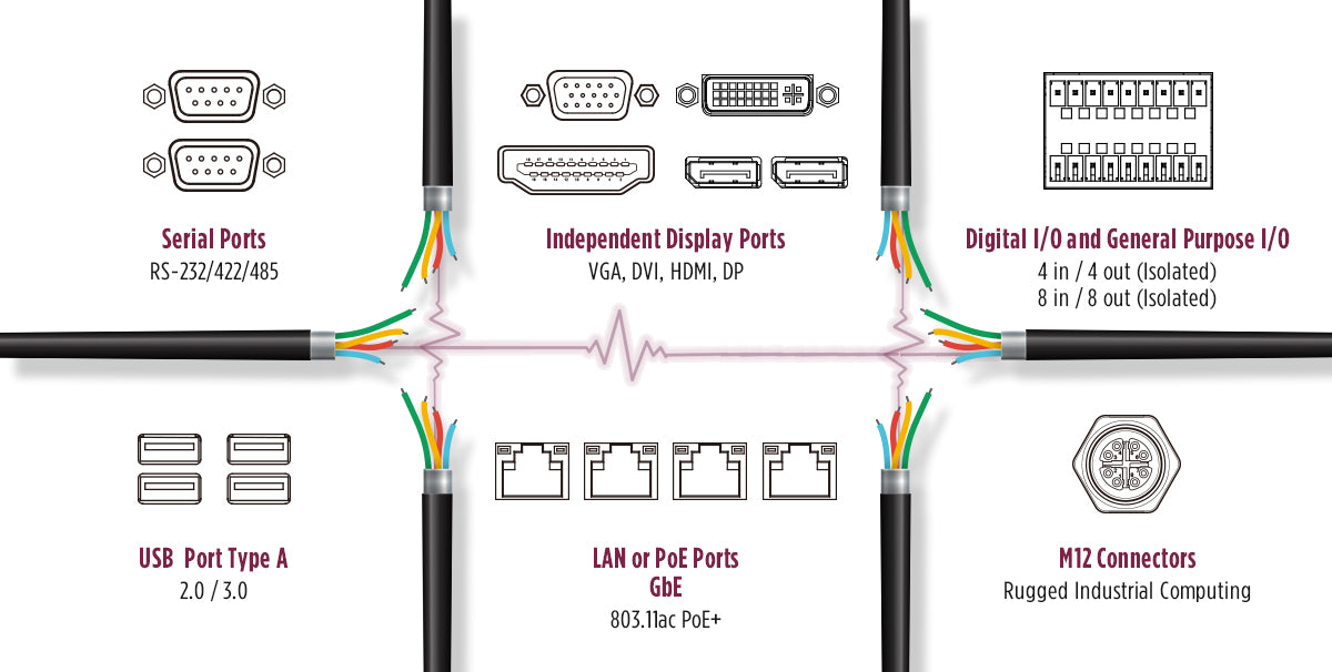
Video Display Ports 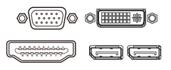

VGA
The original display port was designed by IBM in 1987 for used in their PS/2 systems; known as the VGA (Video Graphics Array) port, this video interface is still being used 32 years later. VGA was designed to use analog signals instead of digital ones. The main limitations of the VGA port was its maximum resolution and it was not designed to be hotpluggable (even though in practice this can be done, it may cause damage to the port and monitor).
DVI
Digital Visual Interface (DVI), released in 1999, was the display interface designed to supersede the VGA port. DVI is based solely on digital signals in order to over the analog limits of the VGA port. DVI can operate in two different modes, depending on the maximum resolution and refresh rate required: single link or dual link. Single link mode can go up to 2560x1600 @ 30Hz, while dual link enables resolution of up to 3840 x 2400 @ 30Hz, which is the standard 4K resolution.
HDMI
High-Definition Multimedia Interface (HDMI), released in 2002, was designed to replace DVI with various enhancements. However, one important distinction is, unlike DVI, HDMI is not an open standard; it is a proprietary interface with an licensing fee associated with its usage. HDMI was originally designed for consumer television sets, so it enables both video and audio transmission, which was missing from the DVI interface. HDMI was designed to be future proof in mind for the maximum resolution and refresh rate. The current HDMI 2.x version can scale up to 8K (7680 x 4320 @ 120Hz). For security and content protection, HDMI can use HDCP (High-bandwidth Digital Content Protection) to encrypt its signals.
DP
Display Port (DP), released in 2008, is an open standard video/audio interface backed by VESA. As such, there are not licensing fees associated with DP. Similar to HDMI, DP was designed to be scalable with respect to data speed, maximum resolution, and refresh rate. DP 2.0 can currently reach up to 10K (10240 x 4320 @ 60Hz). In addition, DP comes with support for augmented/virtual reality (AR/VR) devices such as headset or glasses.
Local Area Network (LAN) and Power Over Ethernet (PoE) 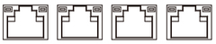

For high speed wired connectivity, the standard RJ45 LAN port is common for industrial and embedded computing; but often times requires setup and a solid network layout to route physical cables. Speeds for the LAN ports can range from 10/100Mbps or up to 10Gbps using standard copper cables, with a maximum cable length of 100m.
10GbE
Networks leveraging 10GbE transmit Ethernet frames at 10 gigabits per second — tenfold the speed of more common GbE connections. 10GbE maintains pace with performance advancements in IoT technology to better supports applications leveraging high-speed storage and I/O. Existing Cat 5e, Cat-6, Cat 6a or dedicated Cat-7 cables support 10GbE transmissions (depending on distance and needed bandwidth), avoiding the need for rewiring. The relative simplicity and speed of 10GbE lets edge computers instantly offload floods of rapidly acquired and processed data onto the enterprise network, providing operators and automated network systems to real-time insights to arrive at proper decisions.
PoE
Standard LAN ports only provide the transmission of data. But in certain use cases such as video security or surveillance, it is desirable to provide power to multiple IoT devices or cameras. This technology is known as “Power Over Ethernet” or PoE for short.
For this purpose, an international standard was created to help integrators of PoE technology adhere to certain specifications. This allows the LAN port to provide both data and power using the same copper cable, eliminating the need for bundling multiple cables. The main advantage of PoE is the elimination of a power outlet, something that is not available in remote or mobile applications. For example, security cameras that are PoE enabled in mass transit or smart city applications benefit from easy maintenance and installation; This is due to a single cable that can provide both data and power efficiently.
DIO and GPIO Ports 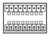

Digital I/O or General Purpose I/O are ports for electrical devices or sensors that do not have common interface such as legacy serial or USB port. These devices can range from alarm sensor, motion detection, or production line automation controllers. By connecting these devices to the system's DIO ports, the device action or trigger can then be controlled by software. For example, an alarm sensor is connected to the DIO's input port, while an alarm alert is connected to the DIO's corresponding output port. The software application can then be programmed to detect a state change in the input port (alarm sensor is triggered) and have the output port change state to trigger the alarm alert to sound an alarm.
Systems typically comes with 4 or 8 or more DIO ports. With multiple input/output ports, this will allow the system to interact with the real world based on different triggering events. The application can then be programmed to trigger from multiple input ports with a series of related actions on the output ports. Expanding on the alarm example above, with multiple output ports, we can program the system not only sound the alarm when it is triggered, but to also call security and close all doors simultaneously. In order to help embedded system developers write their applications based on DIO ports, a sample code package, covering both Windows and Linux OS, is provided to enable programmers to easily access the DIO ports.
M12 Connectors 

Standard connectors, such as network, serial, or USB, on industrial pcs were not designed to be used in rugged environments such as an automotive plant or food processing facility. For these harsh environments, there is a need for a robust, reliable, and hardened connector to ensure the connection between the industiral pcs and the end device will not be disrupted. The M12 connector was designed in 1985 for this purpose; M12 connectors are circular type connector with a 12 mm locking thread. In addition to its build-in locking mechanism, M12 connectors are also rated for IP65, IP68 or higher for waterproof resistant and dustproof protection in washdown and corrosive environments . These connectors are available in various pin count: 3, 4, 5, 8, and 12. The most commonly used pin configuration is the 8 pin M12 connector, which can be adopted for gigabit ethernet LAN/PoE, legacy serial, or USB 2.0 ports.
Common Applications and their pin counts:
- Sensor and power: 3 and 4 pin required
- Profinet and Ethernet: 4 and 8 pin required
- Fieldbus, CANbus and DeviceNet: 4 and 5 pin required
- Signal Integrity: 12 pins
Coding of m12 connectors prevent the incorrect mating from the computer I/O to the connected device. A, B, D, and X code pin outs (see below) are most common and popular in industrial computing. But as the digital transformation demands faster data transmission for high-speed ethernet, the x coded pinout for 10gbit Ethernet will eventually replace the A and D coded pinout for ethernet.
M12 Coding Options for Industrial computing:
-
A-coded for sensors, dc power and 1 Gbit Ethernet
-
B-coded for Profibus
-
C-coded for ac power
-
D-coded for 100 Mbit Ethernet
-
X-coded for 10 Gbit Ethernet
-
S-coded for ac power (will eventually replace C-coded power parts)
- T-coded for dc power (will eventually replace A-coded power parts)
If there are any requirements for industrial computing to help support legacy and new IoT sensors contact Premio engineers to help provide viable solutions to your problem. Contact Premio Here!
References:
1. USB 3.2 Specification Language Usage Guidelines from USB-IF.